
Wednesday, March 2, 2011
OK, quick one.
I am placing Area Boundary Lines on an Area Plan, using Floors as the bases. And it kept driving me crazy that Revit won't snap to the Floor edges. Why?!

Well, it turns out that Revit automatically turns the option "Apply Area Rules" on, which means that it will only snap to walls according to the set area rules. Turning the option off allowed me to snap to everything again:

Thursday, February 3, 2011
I came across this command in my View-tab called Show Hidden Lines and wanted to try it out.

The usage is pretty straight forward: click the command, select the element you want to be "transparent" and then select the element(s) you want to be visible. The result should look something like this:

Well, my colleague also tried it, but the dashed lines would not show up on his screen, even though it was the same file with the same view. Strange.
Even more strange: when printing the view, the lines appeared.
After some searching we found that he had Use Hardware Acceleration in his Options enabled, while I had not:

So, should you find yourself not seeing something on screen that you know should be there, play with this setting. It seems that there are still issues surrounding it.
Monday, January 24, 2011
I've been following the BIM troublemaker for a while now, and he pulled another one out of the hat. For some light reading, just check out this:
http://bimtroublemaker.blogspot.com/2011/01/complex-rigging-and-built-up-forms-pt1.html
and
http://bimtroublemaker.blogspot.com/2011/01/complex-rigging-pt2-skin-that-sucker.html
I thought I was pretty savy with Revit, but the Troublemakes is in a class of his own. I stand amazed.
Friday, December 17, 2010
I am busy creating a schedule for an area plan. I need to get the number of trees that I need to cut down, can keep and plant new. For this I created a Planting family with a few type parametes that change the appearance of the tree (e.g. the Yes/No parameter kappen (which means to cut down in Dutch) is linked to the visibility of a cross across the tree symbol).
So far so good.
I can then create a schedule with my familty types and totals. Cool.

But now I want to only see the trees left at the end of the project.
One option would be to phase the trees (set the phase demolished parameter of all trees to be cut down to the phase of the new construction), but for other reasons I did not want to go that way.
So I figured I would simply set the filter of the schedule and filter out the appropriate family type. But, lo and behold, I don't get that option!

A quick Google-search reveals that this is not a bug but a feature (or something like that).
So for a workaround I am now using the Type Mark parameter, setting it to different values for the different family types. (The other option would have been to create my own shared parameter and attach it to both the project and the family, but I'm just lazy. Plus I can now use this to tag the trees as well.)

But I don't get why I cannot filter based on family type. What would have been the trouble with this? Can someone explain?
Thursday, September 30, 2010
Austodesk has release the 2nd update for Revit 2011. Contrarty to intuition, this can be found under the product download section, rather than the update section for Revit Architecture on the Autodesk site.

At the same time Autodesk has released the latest Subscription Advantage Pack for Revit 2011, including a new type of server for central files, a conceptual energy analysis tool and a set of extensions. I am now downloading all that and will report on my progress later.
Tuesday, September 21, 2010
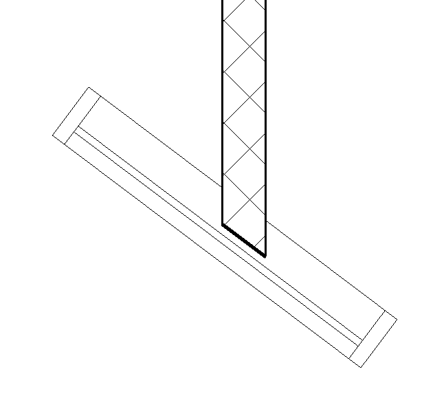
We are in the process of designing a ronded building with an all-glass extgerior. This leads to the situation that an interior wall needs to end at a glass panel. Revit presents with this solution:

The solution that I came up with is a bit of a workaround, but it gets the job done.
First I created a new, very thin wall.

I then drew the thin wall at the angle that the interior wall was supposed to be fased at (parallel to the existing Curtain Wall):

Having done this I cleaned up the result with the Trim tool and adjusted the length of the thin wall:

And that's it. Job done.
Friday, August 27, 2010
 Since I like to work with Revit on my laptop, I was highly irritated when Autodesk decieded to switch to an online-help-only model. It meant that I had to be online to get the "help" (for the times that the Revit-help was actually helpful - not very often).
It seems I am not the only person with this issue and so Autodesk published an article on how to change the online-help to a local help-file. See the article here.
It basically boils down to adding three lines to the Revit.ini file.
Simple as that.[Documentation]
UseHelpServer=1
HelpBrowser=0
On a personal note: This is my 100th post. Happy Birthday to me!
Friday, August 20, 2010
With the arrival of R2011 it is finally, finally possible to align different plans (e.g. floorplans) on different sheets without having to draw pencilmarks on your screen. Here is how it works and how it works better (IMHO):
In a sheet view go to Ribbon > View > Guide Grid

Clicking this will prompt you to give a name to this particular Guide Grid for future reference and use in other Sheets.

After I click OK my entire Sheet will be covered with blue lines and become highly unreadable.


But that's fine for now. I'll just align the View to the Guide Grid by using the Ribbon > Modify > Move command. I am able to use Grids for this (as in my example), but Reference Planes will work as well (which can be handy if you don't have any - or too many - Grids).
OK, so now I know where I want to align the drawing on the sheet. Time to get rid of all those blue lines I don't need. I do this by selecing the Guide Grid and using the blue dots on the sides to make is just as big as really neccessary.

Nice.
Time to create a second Sheet (or open it should you already have one created) and apply this Guide Grid. I do this in the View Properties of the Sheet.

I end up with this:

I now know that this one intersection of the Guide Grid is the one to which I need to align the intersection of Grids 1 and A of my 1st-floor drawing.
Oh, and don't worry. Revit will not plot the Guide Grid, so need to always turn it off again. (Although I find that it just looks nicer to not have it on. Call it a personal quirk.)
Wednesday, July 21, 2010
Today I am following an update course for Revit 2011 and a few handy tips are surfacing.
One of them is the project location. While in Revit 2010 the list of standard cities for the US was very extensive, the Netherlands was represented by exactly two location. That left you going to Google Maps, finding the geo-location data and manually entering them.
Revit 2011 makes this easier. It brings Google Maps to you.
In the Ribbon select Manage > Location

And when you change the dropdown menu for Define Location by to Internet Mapping Service, you get this:

Loving It!
Tuesday, July 20, 2010
This is one of the more drastic changes in Revit 2011. The keyboard shortcuts are handled and set differently.
In R 2010 you had the KeyboarShortcuts.txt file in the Program-directory. By changing this you changed the shortcuts.
R 2011 does things differently. Now you have a nice dialoge-box in which to set the keys:

There are a few rules you have to keep in mind (this is straight from the User Reference Guide):
- A keyboard shortcut can consist of up to 5 unique alphanumeric keys.
- You can specify a keyboard shortcut that uses Ctrl, Shift, and Alt with a single alphanumeric key. The sequence displays in the Press new keys field. For example, if you press Control and Shift and D, it displays as Ctrl+Shift+D.
- If a keyboard shortcut includes Alt, it must also include Ctrl and/or Shift.
- You cannot assign reserved keys.
- You can specify multiple keyboard shortcuts for each Revit tool.
- You can assign the same keyboard shortcut to multiple tools. To select the desired tool when you execute the shortcut, use the status bar. See Using Keyboard Shortcuts.
On one hand I like this a lot, because everything is done within Revit and the changes happen immediately (as opposed to having to restart Revit).
However, there are a few features that I don't really like. Because you can assign the same shortcut to multiple commands there is no collision control. Once you type the command, the status bar will display the options and you can cycle through the different commands with the arrow keys and select the one you want with space (see the User Manual).
I just don't get that. I assign a shortcut to make my life easier, not give me multiple options. It is supposed to save me time, not make me type more and more letters. I would really like an option where you can have collision controle while asigning new shortcuts.
Other than that I am happy. :)
Monday, July 5, 2010
This is more a reminder to myself, but if it helps anyone else - great.
We've been having some stability and speed issues with the new release (R2011). Since a lot of this was graphical, I went to look for the list from Autodesk that has all supported graphics cards in it, together with current driver information.
Since it took me some time to finally track it down, here the link:
Revit Graphics Hardware List
Friday, July 2, 2010
I've been playing around with a variable openings for doors in plan view and never quite worked it out. So I finally sat down and started from scratch to get this settled.
And since this is not only nice to have but also interesting to do (from an academic point of view :) ), I thought I'd share. So here goes.
I first started with a Generic Model - line based.

I then create a Reference Line, to which I will attach my opening door. Just put it at any angle but be sure to start it from the family origin.

Adding an Angular Dimension with a Label will make this puppy move like I want it. But since I want to be clever, I use an "internal" Label for this, calling it aopen and sorting it under "Other". Why? Well, I'll tell you in a second.

First will quickly draw a "door" with a variable thickness (after all, you could also use this family for windows...). I'll use Symbolic Lines to draw a rectangle, attaching one side to the movable Reference Line and adding some labeled Dimensions to it.

OK, so now for the "smart" part. I want this door to display a possible opening of 10 to 170 degrees, and turn off when the opening angle is below 10.
So I create two new parameters, called opening angle (angle) and door visible (yes/no). The first is so the user can change the angle and the second will turn it off automatically. I the program them as following:
aopen = if(opening angle < 10°, 10°, if(opening angle> 170°, 170°, opening angle))
and
Now I just set the Visibility of the door-lines to the door visible parameter and I am done.
Now, when the user enters a value lower than 10 the actual aopen-angle will stay at 10, preventing the family to break, but turning off the visibility. And an automatic doorstopper is set at 170 degrees.
Of course you could also introduce variables to set the minimum and maximum opening angels etc, but hey. That's up to you. :)
Wednesday, June 30, 2010
As I have just found out there is a first update out for Revit 2011:
Revit Architecture Downloads
Revit Structure Downloads
Revit MEP Downloads
Looks like the main things are stability and performance issues.
The About Revit info from the help menu will now display this:

Thanks to the Revit Clinic for the post.
Finally! Abvent finally released the Plugin for Revit 2011.
At first glance things are looking good. The export work just as easy as with the Revit 2010 plugin: create a camera (not perspecitve!) and export from this view. So far so easy.
Unfortunately a few pending issues have not been resolved.
One major drawback is still the inability to export any toposurface properly. No matter whether you have severaldifferent regions, subregions or a combination of the above, each with different materials applied, you get one big blob with the material Default.
This is of course nothing new and the workaround is to save different surfaces in different files and then load them as separate objects into your Artlantis project, but still... A missed chance here.
I wonder if they will ever get this to work.
Thursday, May 27, 2010
To create custom patterns to use in Revit you'll need a very specialized tool: A text editor! (Like Notepad, or better Notepad++) With this you can create a .pat file that contains you pattern(s).
To explain how to set this up I have copied the explanation out of the Revit.pat-file stored in the program installation map of your Revit.
;;revit.pat file v. 3.0 ;;;;;;;;;;;;;;;;;;;;;;;;;;;;;;;;;;;;;;(c) 2000-2003 Autodesk Revit ;;;
This file contains the standard set of custom fill patterns distributed with Autodesk Revit. Since it is part of the standard installation, do not change it. Any changes you make may be lost when you update Revit. To define custom patterns, create a new file using this file as a template.
Fill patterns are also known as hatches and fills.
;;Model vs. Drafting patterns
There are two types of fill patterns in Revit: model and drafting. Model patterns are used to depict real-world elements, such as bricks, shingles, tiles, etc. They are defined and display in model units. An 8x16 inch brick pattern will show exactly 12 courses on an 8-foot-tall wall. A 2-meter-tall wall with a 200x400 mm brick pattern will have 10 courses. Model patterns appear denser at coarser view scales and sparser at finer ones.
Drafting patterns are defined in paper units. If you import the pattern at scale 1 and print at 100% zoom, the pattern's dimensions on paper will be exactly as specified in the file, regardless of view scale. Drafting patterns are used to symbolically denote materials such as steel, concrete, sand, etc.
Drafting patterns are typically defined with smaller numbers than model patterns. Drafting patterns usually contain sizes from 0.04 to 1 inch (1 - 25 mm)model patterns usually contain sizes from 2 to 20 inches (50 - 500 mm). These are guidelines only, not enforced by Revit. Revit's existing restrictions limit the maximum size and density of the patterns, and a review of these restrictions is planned for a future release.
;;Pattern files
Revit pattern files contain custom fill pattern definitions. They are modeled after the AutoCAD hatch pattern files, with a few additions. The file extension is .pat. A file may contain an arbitrary number of patterns. To use the patterns, import the file using the Fill Patterns dialog. See Help for detailed instructions.
If a pattern file contains an error, Revit will not import it. An error message will indicate the erroneous line. Revit may consider a pattern to be too large or too dense. If it does, modify the import scale or the pattern definition. Once a pattern is imported, it is stored in the project, independent of the original file.
;;Pattern file format
All lines must be less than 4096 characters long. Lines beginning with ;% are Revit directives. Lines beginning with are comments. Lines beginning with * begin new pattern definitions. Blank lines are ignored.
The file consists of a prologue followed by pattern definitions. The prologue may contain the following directives:
;%VERSION=3.0
This identifies the file as a Revit Fill Pattern file of the specified version. The version described here is 3.0. Include this directive in your files for future compatibility.
;%UNITS=INCH or
;%UNITS=MM
This describes the units in which patterns are defined. Specifying units in the file is preferred to modifying the import scale. If neither directive is present, Revit will assume that the patterns are defined in inches.
;;Pattern definition format
A pattern definition consists of the name header, type directive and line families. Each one is placed on a separate line. The entire pattern is terminated by the following header or the end of the file.
;;Header format
*name, comment
The name may contain any ASCII characters except for comma. They are shown in the list of imported patterns. The comma and comment are optional. They are ignored by Revit. The header may be followed by one of the following type directives:
;%TYPE=DRAFTING or
;%TYPE=MODEL
If neither directive is present, Revit assumes that it is a drafting pattern.
;;Line families
Each line family is a set of parallel lines that build one "direction" of a pattern. A complete pattern may be defined by several families each defining part of the final, such as the vertical joints of brick coursing. The lines are described in the two dimensions of a face as follows:
angle, x-origin, y-origin, shift, offset, dash, space, dash, space ...
Angle specifies the direction, in degrees, of a set of lines relative to the x-axis. The first line in the set starts at the specified x,y-origin. Parallel lines are drawn as specified by Offset and Shift to fill the entire face. Offset defines the distance between parallel lines. Zero Offset is not allowed. Shift moves the pattern of dashes and spaces along the length of each new parallel line. Shift is ignored if the line is solid. Distances are expressed as decimal numbers (using peroid as the decimal separator) in the units previously specified.
The dash-space sequence defines a repeating pattern of dashes and spaces for a line. If it is omitted, the line is solid. Positive numbers define dashes, negative numbers define spaces, and zero specifies a dot. If you begin a pattern with a space, do not alternate dashes and spaces, or do not end with a space, Revit will introduce tiny dashes or spaces to compensate. Revit expands dots and very short dashes into dashes of a minimum size.
;;Worked example
;%UNITS=INCH
;%VERSION=3.0
*Block 8x16, 8 x 16 blocks running bond
;%TYPE=MODEL
0, 0, 0, 0, 8
90, 0, 0, 8, 8, 8, -8
This pattern is called "Block 8x16" you will see this name when you import it into Revit. It is a model pattern. It has two families of lines. The first family creates the horizontal coursing:
angle = 0 => lines are horizontal
x,y-origin = 0,0
shift = 0 => line pattern is not shifted
offset = 8 => consecutive lines are 8 model inches apart
no line pattern => the line is solid.
The second family creates the vertical joints:
angle = 90 => lines are vertical
x,y-origin = 0,0 => the pattern begins at the same point as the horizontals
shift = 8 => line pattern is is shifted by 8 model inches for consecutive lines
offset = 8 => consecutive lines are 8 model inches apart
dash = 8 => each line is built of 8" dashes and 8" spaces
space = 8 => this pattern repeats until the face boundary
The shift makes the vertical segments appear between alternating pairs of horizontal lines, which appears as 16 inch bricks in interlocking bond.
;;Differences from AutoCAD
Note that when Revit exports its models into AutoCAD formats, such as DWG, it makes sure to comply with the more stringent AutoCAD requirements.
- AutoCAD has an 80-character line size limit, Revit's is 4096.
- AutoCAD allows arbitrary sequences of dashes, spaces and dots, Revit coerces them into dash- space format by inserting zero spaces and dashes.
- AutoCAD has a notion of dots, Revit expands them (including the zero dashes it inserted) into short dashes.
- AutoCAD has a maximum of 6 components to a line pattern, Revit has no limit.
- AutoCAD does not allow spaces in a pattern name, Revit does.
- AutoCAD allows only one pattern per a custom file, with pattern name matching file name, and with the file residing in a known location. Revit has none of these restrictions.
- AutoCAD and Revit utilize different logic to decide whether a pattern is acceptable.
I find this explanation very clear. But in the end, to properly find out houw things work, you'll have to get your hands dirty and just go for try-and-error. That's what I did...
Wednesday, May 26, 2010
Creating "deep" elevations and sections has always been an issue with Revit. Yes, you can add shadow and play a bit with the line weigths, but it just does not cover it all.

Wouldn't it be nice to be able to tell Revit to use a lighter color / linestyle once it goes beyond a certain distance into the drawing? Something like this?

Well, there is a way, even if it is cheating a bit.
What I did was basically putting two sections on top of each other onto the sheet. One section contains the main information, including all annotations, while the other is the background. Here's how I did it.
First I created two sections almost on top of each other:

On one of them (here number 1) I turned on the far scope (adjust the blue, dashed lines) and set it so that the view does not look further than all items in the foreground. This will be my main view with all the info and annotation.
On the other view (# 2) I turned everything grey using the Halftone option in the Visibility/Graphics settings:

I also hid anything I did not need (levels, the site, etc) and turned on the shadows, setting the shadow color to a relatively light color.
In the final step I went to the sheet and placed view #2 first.

This way when I place view #1 it will be displayed above #2 and cover everything that is not background.

Here we go. A nice "deep" section that will automatically update, no matter which item I change.

Saturday, May 22, 2010

Looks like R2011 has been recieved very well.
I am still waiting for the Artlantis Plugin to work before making the switch at the office. I just hope they hurry up!
Wednesday, May 19, 2010
Phew. What a title for a post! But, basically, that's what it is.
To explain: I was looking for a way to make dynamic shelves, where I could not only determine the distance between the individual boards, but also the number of them. Simply put: I want a family where I can say: shelve A has three boards that are 40cm apart, while shelve B has four boards that are 45cm apart.
To get to grips with the technique I first made a trial family, using my trusted cubic meter:

I then set up a family using the Generic Model - Floor Based template, because my cubic meter sits on the floor. You should use the appropriate template when using this technique for other things.
Anyway. I loaded the cube into the family, and placed it at the center of the family. I then created a reference plane to the right and gave it a defined distance with a parameter calles "distance". (If this is too fast for you, please read the manual on dynamic families and labels.)

OK. Now comes the tricky part. I then went ahead and created an array from the cube, and selected the following settings:


So far so good. The next step is to create a parameter for the number of cubes in the array. Select the cube, and a temporary dimension will pop up the the number of items on it. This you can select and add a parameter.

Well. That's it for the basic setup. Now comes the "programming part":
Open the Family Types dialogue box and set it up in the following way:

I then let the distance be calculated by multiplying the number of cubes (minus one) with said distance.
And presto, it works!

Monday, May 10, 2010
We are using Artlantis for our renders at work. Nice software package with lot sof options.
The Revit-plugin for 2011 is supposed to arrive end of May.
Also, there is an update to Studio 3.03 available from their site.
Monday, April 26, 2010
I've had a chance to poke around R2011 a little further, and there are (still) a few things that don't work well - or at all. So here's a short (and propably incomplete) list:
1. Stairs:


2.Formulas
The help states that exp(x) is e to the power of x. So exp(1) should be e (2.7182818...)

3. Selection

4. Help


 Posts
Posts


