Wednesday, August 10, 2011

Thursday, March 24, 2011
Autodesk has released Revit 2012 unto the public. Well, sort of. I've heard of it and seen reviews but could not find anything on the official website.
But in any case David Light has written a quite comprehensive review. Check it out.
From what I'm reading I can't wait to get my hands on this release. Especially the improvements for worksharing look really promissing.
I'll post my experiences once I make them.
Wednesday, March 2, 2011
OK, quick one.
I am placing Area Boundary Lines on an Area Plan, using Floors as the bases. And it kept driving me crazy that Revit won't snap to the Floor edges. Why?!

Well, it turns out that Revit automatically turns the option "Apply Area Rules" on, which means that it will only snap to walls according to the set area rules. Turning the option off allowed me to snap to everything again:

Wednesday, February 16, 2011
Whenever you create a new View via the Ribbon:

You get the following dialogue box:
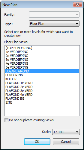
Here you can select for which level you want to create the View. This is the only time you will be able to set the level associated with this View! So choose wisely.
Let me repeat this: You will not be able to change the Level associated with this View!
As you can see here, the field for the associated level is grayed out.

This also means that when you duplicate this View, it will stay with this Level. No amount of renaming the View will change that!
So if you need a view of a different level with the same settings, make use of View Templates instead of blindly copying.
Thursday, February 10, 2011
Almost to the day one year ago I posted Part II of the catenary line. And since I got a comment on if I was ever going to finish it, I thought it about time.
Sadly I don't have the files anymore, but I'll discuss the technique I used back than. I just won't have pictures. Sorry.
To start off there is one addition I have to make to the last post: the parameter nr needs to be an instance parameter!
The next step is to open a new Conceptual Mass and start placing the family created in the previous post. Place the family on the x/z-plane with the origin as insertion point. By changing the nr parameter for each instance to a unique number (with the maximum of 8, since that is what we put down as nr_of_segs as a type parameter) the lines will move and adjust automatically.
At the end you should have a row of lines that form a catenary line. Play around with the parameters to get the exact shape that you want, import it into you project and use the lines to draw trusses, walls, sweeps, or whatever.
I hope this last step works without pictures. Should you have questions, please drop a comment and I'll try to answer them. Good hunting!
Wednesday, February 9, 2011
Getting the North Arrow right on my sheets was not a high priority for me up until now. I mean, if it's about right, it's OK. Right?
Wrong.
I realized that I rely heavily on north arrows put on a sheet by other people and I started asking myself, whether these people unknown knew what they were doing. So to be sure that others using my drawings get the correct information, I asked myself how to do this properly.
I started with getting a situation drawing from official channels. Here I know that North is North. I then proceeded to rotate my Project North so that the first setup of the building aligns with the official map. (Making sure that my View was set to True North.)
Now I know True North and Project North. The angle between them is something like 112,443599125 degrees. About. More or less. Something like that.
Right. Not much help there.
So instead of solving this with numbers I went ahead and drew a "north arrow" with reference planes in this view.
Problem solved.
I can now go into any view and I have my "North Arrow" point to True North. I can then place my North Arrow Symbol correctly on any sheet.
And if I had paid attention as to where I had placed these reference planes in relation to the drawing I might have had the correct insertion point on my sheet as well. But then, that would have required thinking and planning ahead...
Thursday, February 3, 2011
I came across this command in my View-tab called Show Hidden Lines and wanted to try it out.

The usage is pretty straight forward: click the command, select the element you want to be "transparent" and then select the element(s) you want to be visible. The result should look something like this:

Well, my colleague also tried it, but the dashed lines would not show up on his screen, even though it was the same file with the same view. Strange.
Even more strange: when printing the view, the lines appeared.
After some searching we found that he had Use Hardware Acceleration in his Options enabled, while I had not:

So, should you find yourself not seeing something on screen that you know should be there, play with this setting. It seems that there are still issues surrounding it.
Wednesday, January 26, 2011
I've run across a very informative graphic to explain how Revit is set up at the most basic level. I've polished things up a bit and here you are:

Monday, January 24, 2011
I've been following the BIM troublemaker for a while now, and he pulled another one out of the hat. For some light reading, just check out this:
http://bimtroublemaker.blogspot.com/2011/01/complex-rigging-and-built-up-forms-pt1.html
and
http://bimtroublemaker.blogspot.com/2011/01/complex-rigging-pt2-skin-that-sucker.html
I thought I was pretty savy with Revit, but the Troublemakes is in a class of his own. I stand amazed.
Thursday, January 20, 2011
In the past few days I've been back behind my computer, reviting away. And I have found an interesting way Revit understands the difference between Select All Instances and Count in schedules.
Today we needed to calculate the number of workspaces placed in an interior design for a client. So we created a furniture schedule with the fileds Family Name, Family Type and Count. In the options we chose not to Itemize Every Instance and sorted by Family and then by Type. So far so easy.
According to the schedule we had 150 workspaces.
But when I went to one if them and used the Right Click > Select All Instances > Entire Project I got 183 selections back.
Wait. What?
Well after some searching it turns out that Select All Instances > Entire Project will select everything and in all Design Options, whereas the schedule will give you the correct count for the selected Design Option.
Just one of those things that are logical from a certain point of view, but not readily obvious.
Monday, January 3, 2011
To all you Reviteers out there:
Happy New Year!


